The last update on my Arduino-based yard art sculpture showed the addition of a servo to a circuit with eight LEDs.
Today, I want to figure out if I can set the servo and LEDs to activate only after a PIR (passive infrared) motion sensor has been triggered.
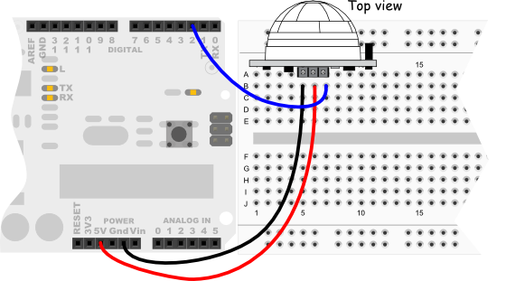
The PIR motion sensor I’ll use for this experiment is sold through Radio Shack (product number 276-135) and available online at Parallax, Inc. (product number 555-28027, rev B).
Via info at Parallax, here’s how to wire the sensor to your Arduino (note: I’m using digital port 12, not 2 as shown):
The question for me is how complex/sophisticated do I want the code for the yard art sculpture to be? For example, let’s look at two code samples, a simple one and one that’s more sophisticated.
/*
 * PIR sensor tester
 */

int ledPin = 13;                // choose the pin for the LED
int inputPin = 2;               // choose the input pin (for PIR sensor)
int pirState = LOW;             // we start, assuming no motion detected
int val = 0;                    // variable for reading the pin status

void setup() {
  pinMode(ledPin, OUTPUT);      // declare LED as output
  pinMode(inputPin, INPUT);     // declare sensor as input

  Serial.begin(9600);
}

void loop(){
  val = digitalRead(inputPin);  // read input value
  if (val == HIGH) {            // check if the input is HIGH
    digitalWrite(ledPin, HIGH);  // turn LED ON
    if (pirState == LOW) {
      // we have just turned on
      Serial.println("Motion detected!");
      // We only want to print on the output change, not state
      pirState = HIGH;
    }
  } else {
    digitalWrite(ledPin, LOW); // turn LED OFF
    if (pirState == HIGH){
      // we have just turned of
      Serial.println("Motion ended!");
      // We only want to print on the output change, not state
      pirState = LOW;
    }
  }
}
/*
 * //////////////////////////////////////////////////
 * //making sense of the Parallax PIR sensor's output
 * //////////////////////////////////////////////////
 *
 * Switches a LED according to the state of the sensors output pin.
 * Determines the beginning and end of continuous motion sequences.
 *
 * @author: Kristian Gohlke / krigoo (_) gmail (_) com / http://krx.at
 * @date:   3. September 2006
 *
 * kr1 (cleft) 2006
 * released under a creative commons "Attribution-NonCommercial-ShareAlike 2.0" license
 * http://creativecommons.org/licenses/by-nc-sa/2.0/de/
 *
 *
 * The Parallax PIR Sensor is an easy to use digital infrared motion sensor module.
 * (http://www.parallax.com/detail.asp?product_id=555-28027)
 *
 * The sensor's output pin goes to HIGH if motion is present.
 * However, even if motion is present it goes to LOW from time to time,
 * which might give the impression no motion is present.
 * This program deals with this issue by ignoring LOW-phases shorter than a given time,
 * assuming continuous motion is present during these phases.
 *
 */

/////////////////////////////
//VARS
//the time we give the sensor to calibrate (10-60 secs according to the datasheet)
int calibrationTime = 30;

//the time when the sensor outputs a low impulse
long unsigned int lowIn;

//the amount of milliseconds the sensor has to be low
//before we assume all motion has stopped
long unsigned int pause = 5000;

boolean lockLow = true;
boolean takeLowTime;

int pirPin = 3;    //the digital pin connected to the PIR sensor's output
int ledPin = 13;

/////////////////////////////
//SETUP
void setup(){
  Serial.begin(9600);
  pinMode(pirPin, INPUT);
  pinMode(ledPin, OUTPUT);
  digitalWrite(pirPin, LOW);

  //give the sensor some time to calibrate
  Serial.print("calibrating sensor ");
    for(int i = 0; i < calibrationTime; i++){
      Serial.print(".");
      delay(1000);
      }
    Serial.println(" done");
    Serial.println("SENSOR ACTIVE");
    delay(50);
  }

////////////////////////////
//LOOP
void loop(){

     if(digitalRead(pirPin) == HIGH){
       digitalWrite(ledPin, HIGH);   //the led visualizes the sensors output pin state
       if(lockLow){
         //makes sure we wait for a transition to LOW before any further output is made:
         lockLow = false;
         Serial.println("---");
         Serial.print("motion detected at ");
         Serial.print(millis()/1000);
         Serial.println(" sec");
         delay(50);
         }
         takeLowTime = true;
       }

     if(digitalRead(pirPin) == LOW){
       digitalWrite(ledPin, LOW);  //the led visualizes the sensors output pin state

       if(takeLowTime){
        lowIn = millis();          //save the time of the transition from high to LOW
        takeLowTime = false;       //make sure this is only done at the start of a LOW phase
        }
       //if the sensor is low for more than the given pause,
       //we assume that no more motion is going to happen
       if(!lockLow && millis() - lowIn > pause){
           //makes sure this block of code is only executed again after
           //a new motion sequence has been detected
           lockLow = true;
           Serial.print("motion ended at ");      //output
           Serial.print((millis() - pause)/1000);
           Serial.println(" sec");
           delay(50);
           }
       }
  }
Conclusion?
So, what do you think? Should I go with the first or second code sample for the yard art sculpture?
I’ll get input from you — the loyal, happy reader — and let everyone else know what you said. Then, I’ll show you what I did and if it differs from you, I’ll try your suggestions and show the world the results.
Until next time!